|
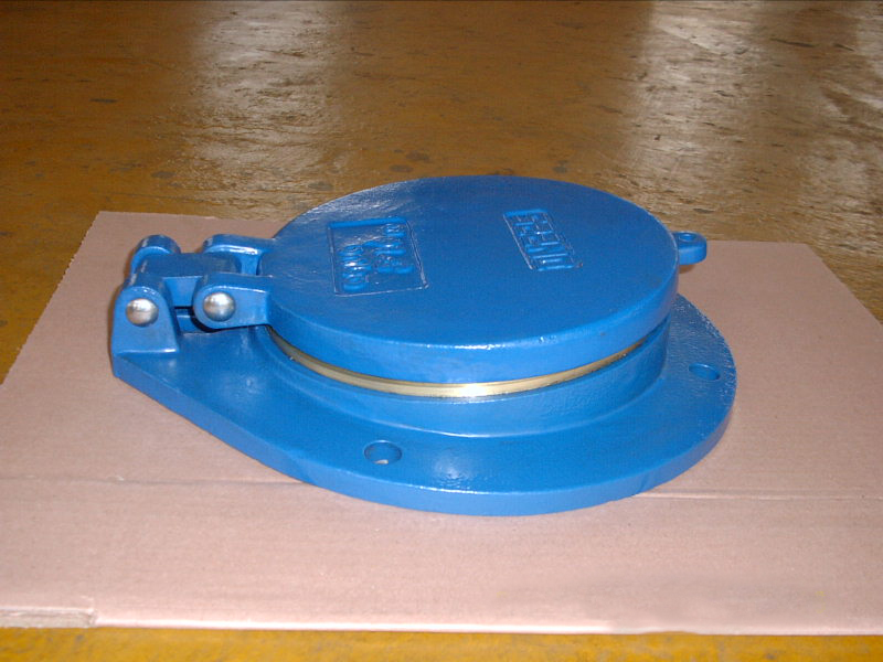
Flap valves, which are essential one-way sealing components at pipe outlets, require careful attention to their installation height. The height at which they are installed significantly influences their effectiveness in preventing backflow and minimizing the risk of water hammer. If the flap valve is installed too high, it may result in seal failure and allow backflow. Conversely, if it is installed too low, it can heighten the impact of water hammer and increase flow resistance. Scientific design must be based on operating parameters and combined with the pipe outlet environment, achieving dual goals of backflow prevention and water hammer resistance through "height adaptation + auxiliary measures."
I. Core Principles of Installation Height Design
1. Water Level Adaptation Principle: For drainage pipe outlets, the flap valve installation height should be lower than the maximum water level of the receiving water body to enhance sealing and prevent air entry-induced water hammer, while being higher than the minimum water level to avoid sediment clogging. For water intake pipe outlets, the height must be above the minimum water level to ensure smooth valve plate opening.
2. Water Hammer Buffering Principle: Avoid installing flap valves close to the water bottom or hard objects; reserve a buffer distance of no less than 1/3 of the flap valve diameter. For high-head and large-flow pipes, adjust the height based on water hammer calculations to optimize the flow regime.
3. Backflow Prevention Bottom Line Principle: The sealing surface must be lower than the maximum backflow water level. Municipal pipes should be below the 100-year return period maximum water level of the receiving water body, and industrial wastewater pipes require additional safety margins to prevent seal failure.
II. Installation Height Standards for Different Working Conditions
1. Conventional Drainage Pipes: Applicable to low-head, medium-small flow scenarios such as clean water and rainwater. The sealing surface should be flush with or 5-10cm below the normal water level; for stable water levels, this can be extended to 10-15cm to balance sealing and flow efficiency.
2. High-Head/Large-Flow Pipes: For pump station outlets and industrial water transmission, the installation height must be determined via water hammer simulation—usually 10-20cm above the normal water level. For high working pressure, raise it by 20-30cm and equip it with water hammer arresters or slow-closing devices.
3. Pipes with Corrosive/Impurity-Containing Media: The sealing surface should be 15-20cm below the maximum water level and over 20cm above the minimum water level. Install sewage outlets or flushing devices underneath to prevent impurity accumulation from affecting valve plate operation.
III. Auxiliary Optimization and Installation Details
1. Water Hammer Protection: Install slow-closing check valves or water hammer arresters upstream of high-head pipes; use elastic rubber hinges or hydraulic buffer devices for valve plates to reduce rigid impact.
2. Backflow Prevention Enhancement: Adopt a "flap valve + weir" combination in tide-affected areas. Use wear-resistant and corrosion-resistant materials for sealing surfaces to compensate for installation deviations via elasticity.
3. Installation Specifications: Make sure the opening and closing direction of the valve plate is aligned with the flow of water, with an opening angle of at least 60°. When tightening the flange bolts, do so symmetrically to maintain the flap valve's position perpendicular to the pipe. Additionally, ensure there is sufficient space for flow diffusion when installing the valve near shores or walls.
IV. Correction of Common Design Misunderstandings
1. Excessively low installation causing valve plate clogging: Determine height based on minimum water level + sediment accumulation height, reserving 15-20cm for sewage discharge.
2. Low installation of high-head pipes intensifying water hammer: Raise to 10-20cm above the maximum water level and use slow-closing devices.
3. Ignoring seasonal water level fluctuations: Take the multi-year average minimum water level as the benchmark, adjust for fluctuations, and install adjustable brackets if necessary.
All in all, the design of the installation height for flap valves must strike a balance between adapting to water levels, buffering against water hammer, and preventing backflow. By conducting precise calculations based on the working conditions and implementing supporting auxiliary measures, potential hazards can be significantly reduced, ensuring the stable operation of the piping system.
|